
When our software developers take time out in The Shed, our maker space where we try out new technologies and hardware, we never quite know what ideas will surface. But thanks to one software developer’s ingenious creativity we’re now the proud owners of a patent for a method that uses seeds instead of ink to create images.
Former Global Graphics’ software developer Andy Cardy invented the method from a process we use in the printing industry known as screening or half toning. Screening takes a source image with a wide color gamut and creates an output raster format which determines the position and size of droplets of ink required by the printer to recreate the original image.
With this new patent, instead of the output raster format controlling droplets of ink on a printer, it determines:
- which plant or seed is planted to create a color reproduction of the original image, allowing for variable space in the reproduction, for example larger drop sizes could represent large foliage plants;
- how deep the seed is planted, for variable images throughout the growing season;
- where the seed is planted;
- and how many seeds are planted.
The screening process and output also takes into account variables such as soil color and its properties. By incorporating these variables, the method guarantees that the final plant-based reproduction appears visually accurate, accounting for the natural hues that may appear between plants, just like we would consider the substrate in the printing industry.
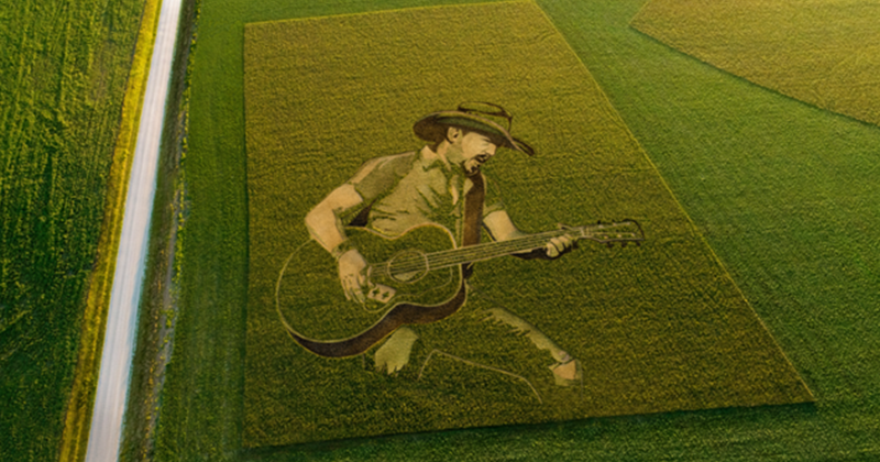
The approach could be suitable for a range of applications including large-scale advertisements, especially on busy flight paths, public artwork and even fallow farmland, where wild bird seed or nectar and pollen sources could be sown in an advertisement image, benefiting both wildlife and the farmer.
Aside from advertising, this technology could be used in place of any activity that would use weed killer or the ploughing of unwanted crops. This could include the methods used to create maize mazes, which are becoming a popular supplemental income option for farmers. The current method of creation is to sow the whole field, then destroy the crop that’s no longer required, tracked by GPS. Instead, this technology would simply avoid planting seeds where they are not required.
Of course, we know from our own gardening experience that things don’t always grow as planned, but there’s a chance we could say goodbye to hours of painstaking work to create that advertisement in a field of crops and hello to a new wave of agricultural artistry!
Be the first to receive our blog posts, news updates and product news. Why not subscribe to our monthly newsletter? Subscribe here
Follow us on LinkedIn, Twitter and YouTube